
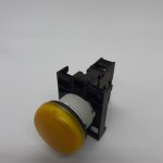
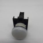
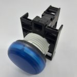
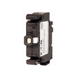
M22-L-B/K-B 210034 LÁMPARA RASANTE AZUL CON LED 12-24VAC/DC
Disponibilidad:
Lampara rasante azul con LED 12-24VAC/DC
- Descripción
- Valoraciones (0)
Descripción
Lámp.señaliz.,plano,azul
Referencia M22-L-B
Código 216775
Anillo frontal dorado # 274150
LEDs para lámparas de señalización # 216557 ff.
Lentes para lámparas de señalización# #216453
Gama de productos
| Color | |||
| Azul | |||
| Ejecución | Rasante |
Generalidades
| Normas y disposiciones | CEI/EN 60947
VDE 0660 |
||
| Grado de protección (IEC/EN 60529, EN50178, VBG 4) | Lámpara de señalización, compacta: IP67, IP69KIndicador acústico, compacto: IP40Potenciómetro, IP40 | ||
| Resistencia climática | Calor húmedo, constante, según IEC 60068-2-78
Calor húmedo, cíclico, según IEC 60068-2-30 |
||
| Temperatura ambiente | °C | ||
| al aire | °C | – 25 … 70 | |
| Posición de montaje | Cualquiera | ||
| Seguridad contra golpes según IEC 60068-2-27
Duración de choque 11 ms, semisinusoidal |
g | > 30 |
Circuitos de corriente
| Tensión asignada soportada al impulso | Uimp | V AC | 4000 |
| Tensión asignada de aislamiento | Ui | V | 2500 |
| Categoría de sobretensión/ grado de contaminación | III/3 |
Dimensiones
| Pulsador y lámpara de señalización con clip telescópico M22-TC y prolongador M22-TCV
Carril DIN según IEC/EN 60715 |
Adaptador de fijación
Referencia M22-A
Código 216374
Para elementos de contacto M22-(C)K… y elementos LED M22-(C)LED…
Números de orden en el adaptador de fijación
Gama de productos
| Adaptador de fijación (fijación frontal) para 3 elementos de contacto/LED
Para elementos de contacto M22-(C)K… y elementos LED M22(C)LED… Números de orden en el adaptador de fijación |
|||
| Fijación | Fijación frontal | ||
| Equipamiento contactos: = función de seguridad, mediante maniobra positiva de apertura según IEC/EN 60947-5-1 | |||
| C = Contacto de cierre | – | ||
| A = Contacto de apertura | – | ||
| Asignación | |||
| Para 1 elemento de función M22-SWD-K… o elemento de LED
M22-SWD-LED… Adicionalmente posibilidad de 1 o 2 elementos de contacto M22K.. Número de orden en el adaptador de fijación. |
|||
| Nota para el encabezamiento
Definición del adaptador de fijación con números de referencia seg x = Número de orden en el adaptador de fija y = Número de función en el elemento de contacto |
ún EN 50013
ción |
||
Generalidades
| Normas y disposiciones | CEI/EN 60947
VDE 0660 |
||
| Longevidad, mecánica | Maniobras | 6 × 10 | >5 |
| Frecuencia de maniobras | Maniobra/h | 3600 | |
| Par de giro de accionamiento (bornes roscados) | Nm | 0.8 | |
| Grado de protección (IEC/EN 60529, EN50178, VBG 4) | IP20 | ||
| Resistencia climática | Calor húmedo, constante, según IEC 60068-2-78
Calor húmedo, cíclico, según IEC 60068-2-30 |
||
| Temperatura ambiente | °C | ||
| al aire | °C | – 25 … 70 | |
| Posición de montaje | Cualquiera | ||
| Seguridad contra golpes según IEC 60068-2-27 Duración de choque 11 ms, semisinusoidal | g | > 30 |
Circuitos de corriente
| Tensión asignada soportada al impulso | Uimp | V AC | 6000 |
| Tensión asignada de aislamiento | Ui | V | 500 |
| Categoría de sobretensión/ grado de contaminación | III#3 | ||
| Seguridad contra fallo de conexión | |||
| con 24 V DC/5 mA | HF | Frecuencia de errores | -7 7
< 10 , < 1 fallo por cada 10 maniobras |
| con 5 V DC/1 mA | HF | Frecuencia de errores | -6 6
< 5 × 10 , < 1 fallo por cada 5 × 10 maniobras |
| Resistencia a cortocircuitos máx. | |||
| sin fusibles | Referencia | PKZM0–10/FAZ-B6/1 | |
| Con fusibles | gG/gL | A | 10 |
Poder de corte
| Intensidad asignada de empleo | Ie | A | |
| AC-15 | |||
| 115 V | Ie | A | 6 |
| 230 V | Ie | A | 6 |
| 400 V | Ie | A | 4 |
| 500 V | Ie | A | 2 |
| DC-13 | |||
| 24 V | Ie | A | 3 |
| 42 V | Ie | A | 1.7 |
| 60 V | Ie | A | 1.2 |
| 110 V | Ie | A | 0.8 |
| 220 V | Ie | A | 0.3 |
| Longevidad eléctrica | |||
| AC-15 | |||
| 230 V/0.5 A | Maniobras | 6 × 10 | 1.6 |
| 230 V/1.0 A | Maniobras | 6 × 10 | 1 |
| 230 V/3.0 A | Maniobras | 6 × 10 | 0.7 |
| DC-13 | |||
| 12 V/2.8 A | Maniobras | 6 × 10 | 1.2 |
| Elementos de contacto |
Generalidades
| Normas y disposiciones | IEC/EN 60947
VDE 0660 |
||
| Posición de montaje | Cualquiera |
Condiciones ambientales mecánicas
| Grado de protección (IEC/EN 60529, EN50178, VBG 4) | IP20 | ||
| Condiciones ambientales climáticas | |||
| Temperatura ambiente de servicio (IEC 60068-2) | °C | + 70 | |
| Elemento de función | |||
| Fijación | Fijación frontal | ||
| Espacio interior y colocación exterior protegida |
Dimensiones
| Adaptador de fijación |
DATASHEET – M22-LED-B
Delivery program
| Product range | Accessories | ||
| Part group reference (e.g. DIL) | M22 | ||
| Basic function accessories | LED elements | ||
| Single unit/Complete unit | Single unit | ||
| Connection technique | Screw terminals | ||
| Fixing | Front fixing | ||
| Rated operational voltage | Ue | V | 12 – 30 V AC/DC, 50/60 Hz |
| Rated operational current | Ie | mA | 8 – 15 |
| Power consumption | Pmax. | W | 0.26 |
| Lifespan to EN 60064 at ta = +25 °C | tmean (AC) | h | 100000 |
| Degree of Protection | IP20 | ||
| at 24 V | |||
| Colour | |||
| Connection to SmartWire-DT | no | ||
| Approval | |||
| Actuator travel and actuation force as per DIN EN 60947-5-1, K.5.4.1 | |||
| Minimum force for positive opening | N | 0 | |
| Connection technique | Screw terminals | ||
| Notes
For indicator lights, illuminated pushbutton actuators, and illuminated selector switch actuators, the following applies: M22…-R only in combination with M22-LED…-R M22…-G only in combination with M22-LED…-G M22…-W only in combination with M22-LED…-W M22…-Y only in combination with M22-LED…-W M22…-B in combination with M22-LED…-W or M22-LED…-B |
|||
Technical data
General
| Standards | IEC 60947-5-1 | ||
| Operating torque (screw terminals) | Nm | ≦ 0.8 | |
| Degree of Protection | IP20 | ||
| Climatic proofing | Damp heat, constant, to IEC 60068-2-78 |
08/16/2018 1 / 3
| Damp heat, cyclic, to IEC 60068-2-30 | |||
| Ambient temperature | |||
| Open | °C | -25 – +70 | |
| Storage | °C | – 40 – + 80 | |
| Mounting position | As required | ||
| Mechanical shock resistance according to IEC 60068-2-27 Shock duration 11 ms, half-sinusoidal | g | > 30 | |
| Mechanical shock resistance | g | 30
Shock duration 11 ms Sinusoidal according to IEC 60068-2-27 |
|
| Terminal capacities | mm2 | ||
| Solid | mm2 | 0.75 – 2.5 | |
| Stranded | mm2 | 0.5 – 2.5 |
Contacts
| Rated impulse withstand voltage | Uimp | V AC | 6000 |
| Rated insulation voltage | Ui | V | 500 |
| Overvoltage category/pollution degree | III/3 | ||
| Indoor and protected outdoor installation |
Design verification as per IEC/EN 61439
| Technical data for design verification | |||
| Rated operational current for specified heat dissipation | In | A | 0 |
| Heat dissipation per pole, current-dependent | Pvid | W | 0 |
| Equipment heat dissipation, current-dependent | Pvid | W | 0 |
| Static heat dissipation, non-current-dependent | Pvs | W | 0.45 |
| Heat dissipation capacity | Pdiss | W | 0 |
| Operating ambient temperature min. | °C | -25 | |
| Operating ambient temperature max. | °C | 70 | |
| IEC/EN 61439 design verification | |||
| 10.2 Strength of materials and parts | |||
| 10.2.2 Corrosion resistance | Meets the product standard’s requirements. | ||
| 10.2.3.1 Verification of thermal stability of enclosures | Meets the product standard’s requirements. | ||
| 10.2.3.2 Verification of resistance of insulating materials to normal heat | Meets the product standard’s requirements. | ||
| 10.2.3.3 Verification of resistance of insulating materials to abnormal heat and fire due to internal electric effects | Meets the product standard’s requirements. | ||
| 10.2.4 Resistance to ultra-violet (UV) radiation | Meets the product standard’s requirements. | ||
| 10.2.5 Lifting | Does not apply, since the entire switchgear needs to be evaluated. | ||
| 10.2.6 Mechanical impact | Does not apply, since the entire switchgear needs to be evaluated. | ||
| 10.2.7 Inscriptions | Meets the product standard’s requirements. | ||
| 10.3 Degree of protection of ASSEMBLIES | Does not apply, since the entire switchgear needs to be evaluated. | ||
| 10.4 Clearances and creepage distances | Meets the product standard’s requirements. | ||
| 10.5 Protection against electric shock | Does not apply, since the entire switchgear needs to be evaluated. | ||
| 10.6 Incorporation of switching devices and components | Does not apply, since the entire switchgear needs to be evaluated. | ||
| 10.7 Internal electrical circuits and connections | Is the panel builder’s responsibility. | ||
| 10.8 Connections for external conductors | Is the panel builder’s responsibility. | ||
| 10.9 Insulation properties | |||
| 10.9.2 Power-frequency electric strength | Is the panel builder’s responsibility. | ||
| 10.9.3 Impulse withstand voltage | Is the panel builder’s responsibility. | ||
| 10.9.4 Testing of enclosures made of insulating material | Is the panel builder’s responsibility. | ||
| 10.10 Temperature rise | The panel builder is responsible for the temperature rise calculation. Eaton will provide heat dissipation data for the devices. | ||
| 10.11 Short-circuit rating | Is the panel builder’s responsibility. The specifications for the switchgear must be observed. | ||
| 10.12 Electromagnetic compatibility | Is the panel builder’s responsibility. The specifications for the switchgear must be observed. | ||
| 10.13 Mechanical function | The device meets the requirements, provided the information in the instruction leaflet (IL) is observed. |
08/16/2018 2 / 3
Technical data ETIM 6.0
| Low-voltage industrial components (EG000017) / Lamp holder block for control circuit devices (EC000204) | |||
| Electric engineering, automation, process control engineering / Low-voltage switch technology / Command and alarm device / Bulb socket block for command and alarm devices
(ecl@ss8.1-27-37-12-09 [AKF027011]) |
|||
| With integrated transformer | No | ||
| With integrated voltage decreasing resistor | No | ||
| With integrated lamp | Yes | ||
| With integrated diode | Yes | ||
| Lamp holder | None | ||
| Rated voltage Ue at AC 50 Hz | V | 12 – 30 | |
| Rated voltage Ue at AC 60 Hz | V | 12 – 30 | |
| Rated voltage Ue at DC | V | 12 – 30 | |
| Voltage type for actuating | AC/DC | ||
| Type of lamp | LED | ||
| Connection type auxiliary circuit | Screw connection | ||
| Colour lamp | Blue | ||
| Type of fastening | Front fastening | ||
Approvals
| Product Standards | IEC/EN 60947-5; UL 508; CSA-C22.2 No. 14-05; CSA-C22.2 No. 94-91; CE marking | ||
| UL File No. | E29184 | ||
| UL Category Control No. | NKCR | ||
| CSA File No. | 012528 | ||
| CSA Class No. | 3211-03 | ||
| North America Certification | UL listed, CSA certified | ||
| Degree of Protection | UL/CSA Type: – |
Dimensions
| A = 37.2 |
| Pushbutton with M22-(C)K…
Pushbutton with M22-(C) LED… + M22-XLED… |
Additional product information (links)
| IL04716002Z (AWA1160-1745) RMQ-Titan System | |
| IL04716002Z (AWA1160-1745) RMQ-Titan System | ftp://ftp.moeller.net/DOCUMENTATION/AWA_INSTRUCTIONS/IL04716002Z2018_05.pdf |
Solo los usuarios registrados que hayan comprado este producto pueden hacer una valoración.


Valoraciones
No hay valoraciones aún.